Making phone calls at three-minute intervals. Those born before the year 2000 may still remember: in the past, the length of time for a unit charge in the local or regional area of many countries was three minutes.

In Germany, this applied from 1889 and, depending on the provider and the rate, until the 2000s. Today, billing by the minute or second is common.
The first telephone booth in Germany was installed in Berlin in 1881, followed in 1899 by the coin-operated telephone, i.e., telephone booths for closed rooms, such as post offices, hotels or theater lobbies. For a long time, telephones in one’s own home were a luxury item and therefore correspondingly rare.

In the early days of telephony, all calls between two parties had to be switched by hand. Since this was mostly done by women, they were also called ‘Fräulein vom Amt’ (switchboard girl). In 1907, there were about 16,000 of them nationwide! Automation of the exchanges began as early as 1908, but it was not until 1966 that all local networks in the territory of the old Federal Republic of Germany were automated!
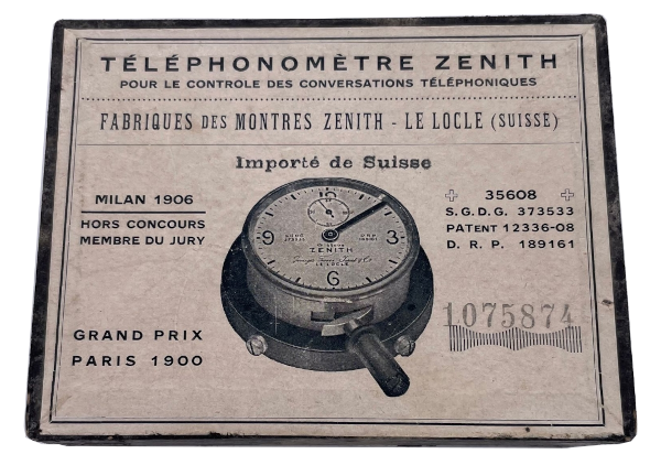
The Telephonometer (Téléphonomètre in French) by the Swiss watch manufacturer Zenith shown above was a useful tool in the world of the three-minute telephone call. It was used by the switchboard girl to correctly determine the duration of the call for billing purposes and to indicate to the user via a visual signal that three more minutes of talk time were about to expire.
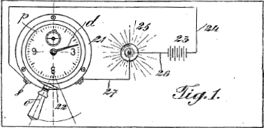
For this purpose, the device has two connections on the outside, each of which are short-circuited for a few seconds shortly before three minutes elapse, i.e. they serve as switches. This can be used, for example, to switch a light in the telephone booth on and off again. A short video shows this:
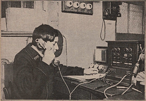
Of course, a corresponding optical signaling could also take place simultaneously in the exchange itself. The following picture shows an exchange from the 1920s. Three Telephonometers can be seen on the left hand side.
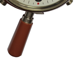
The Telephonometer has a diameter of 60 mm (without lever) and a height of 29 mm. The long lever on the Telephonometer has several functions at once:
- Lever to the right: Start
- Lever to the left: Stop
- Push lever further to the left: Zeroing the minute hand and winding the mainspring
The second hand is not reset when zeroing, so it remains somewhere. It’s not very useful anyway, since it only counts from 0 to 48 seconds instead of 60. At least, you can see very quickly from the second hand whether the movement is running at all.
After twelve minutes, the movement actually stops and has to be restarted. True to the principle: Keep it short!
Zenith has patented the functionality of the Telephonometer and some further developments of it in Switzerland, Germany, France and Great Britain:
- CH35608
Georges Favre-Jacot, 1906: Compteur avertisseur électrique pour contrôler la durée des conversations téléphoniques. - CH45850, CH64799, CH68282, CH96392, CH99414, CH102867
Further developments of the above patent between 1908 and 1922. - DE189161
Georges Favre-Jacot, 1906: Signalvorrichtung zum Anzeigen der für Telefongespräche zulässigen Dauer. - FR373533
Georges Favre-Jacot, 1907: Compteur avertisseur électrique pour contrôler la durée des conversations téléphoniques. - GB12336 von 1908 (GB190812336)
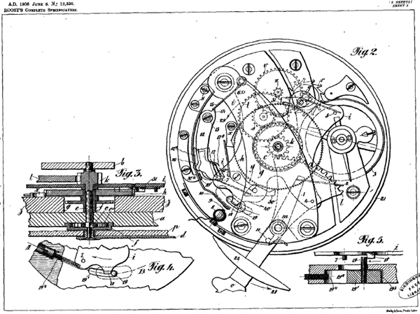
Hermann Roost, 1908: Electric Indicating Meter for Controlling the Duration of Telephone Conversations.
Herman Roost was probably the actual developer of the movement at Zenith.
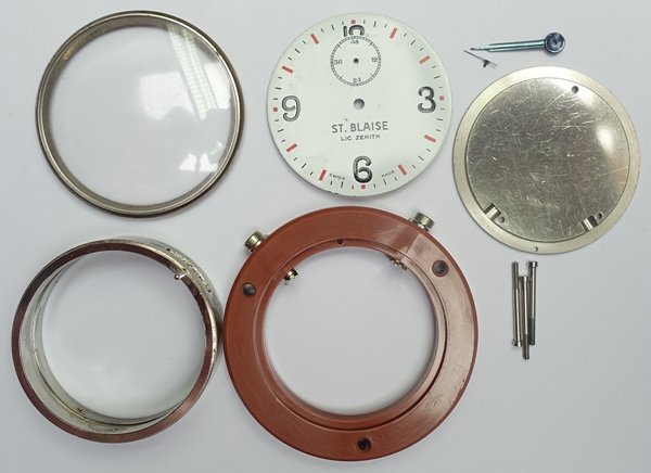
Perhaps you noticed on the video above that it is a different Telephonometer than the one shown at the very top? On the dial it says:
ST. BLAISE
LIC. ZENITH
So Zenith licensed the production of the Telephonometer to the Fabrique d’Horlogerie de Saint-Blaise S.A. (STB) in Switzerland. Unfortunately, I do not know from when this was the case. In any case, not before 1924, since this was the founding year of STB. The movements used are technically identical, older STB telephonometers even have movements labeled ZENITH.
Time to take a closer look at the inner mechanism of a Telephonometer. First, however, the movement has to be removed from the case, which is unfortunately not quite trivial here:
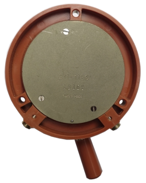
- Snap off metal rim with glass
- Unscrew the bottom cover
- Pull off the middle part of the plastic case (with the external connections) to the back
- Unscrew lever and push movement incl. dial out to the front
- Lift off the hands
For the minute hand, you need a special tool, since it is pressed on very tightly. - Remove dial (screws on the side of the movement)

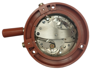
This is what the disassembled movement looks like, here a St. Blaise marked ZENITH.

And this is what an original from ZENITH looks like, bearing the reference 201:
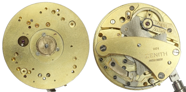
Newer St. Blaise movements without ZENITH hallmark bear the caliber mark STB 211 under the balance:

Technical data of the movements:
- Diameter 19”’ (42.8 mm)
- Hight 13.0 mm
- Swiss lever escapement
- Nickel balance with flat hairspring
- Beat rate 22,500 bph
Very unusual beat frequency, but this is confirmed in a French article from around 1920:
Jean Goyer: Le téléphonomètre indique le nombre et la durée des conversations téléphoniques - 7 Jewels
First, let’s remove the large bridge of the movement. Underneath, a gear segment is revealed, which is connected to the lever of the movement and serves to wind the movement again. The pinion in the center of the movement sits on the axle of the center wheel. On it sits the minute hand on the dial side.
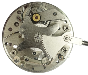
A somewhat bulky metal plate then appears under the gear segment. It is used to short-circuit the two external contacts of the telephonometer shortly before the end of each three minutes. For this purpose, there are pins on the underside of the blue-marked points that press the lamella marked with green lines against one of the contact points (green circle at the top of the picture). The second contact point is also marked with a green circle.
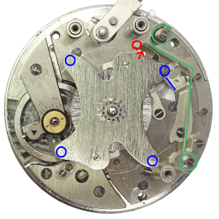
The bulky metal plate has yet another function. At the point with the red arrow, there is a nose that hits a limiting pin (red circle) after 12 minutes have elapsed, thus stopping the movement. When the movement is reset via the lever, the metal plate is turned back by 360°. The following video shows the movement in fast motion. You can also see how the lamella is pressed against the upper contact point.
This is what the back of the metal plate looks like:
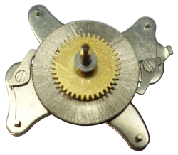
The gold-colored wheel is the center wheel, which is connected to the gear train. The silver-colored wheel initially looks like a barrel, but it isn’t, it’s just a large wheel with very fine gearing. Both wheels are pressed together and sit loosely on the metal plate. The two clicks on the side engage the silver wheel when the movement runs down, i.e. when the center wheel rotates, and thus turn the metal plate as well.
Unfortunately, the thin springs of these clicks are bent or broken off in many Telephonometer movements. If necessary, they can be replaced by bent click springs from other movements. By the way, the screws of the pawls have a left-hand thread, even if they do not have three slots on all movements to indicate a left-hand thread!
Let’s look one level deeper into the movement:
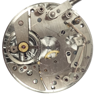
On the right side you can see the parts that are needed for short circuiting the external connections. Slightly to the left of them, you can see two more clicks, which are unfortunately in the wrong position in the picture. The teeth should point in the direction of the center of the movement. They also engage the large silver-colored wheel, but a bit deeper than the two clicks shown above. These clicks here prevent the mainspring from turning back when winding the. Just like a normal movement, but there is only one click.
Speaking of the mainspring, where is it actually located? On the dial side in the middle of the movement! The axle of the center wheel is also the mainspring barrel core. The following picture shows a section of the movement with assembled and disassembled mainspring barrel:
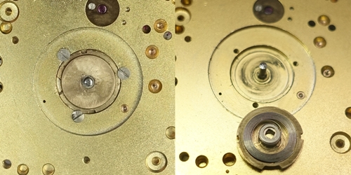
The barrel is fixed by three screws, so it cannot rotate. In a normal movement, the mainspring barrel rotates during winding, while the mainspring core remains fixed by the click. So here, only the center minute wheel can rotate, both when winding and when unwinding. The small notches at the edge of the mainspring barrel are used to preload the mainspring by hand. To do this, you loosen the screws a little bit and turn the mainspring barrel about three full turns to the right. Then the screws are tightened again. This largely winds the mainspring. During the 12-minute running time of the movement, it is only released a little.
Let’s continue with the movement. After removing the gear train bridge:
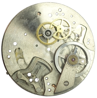
It looks pretty empty there. Above the center is the third wheel, which is driven by the center wheel. It’s followed by the fourth wheel, the escape wheel, the pallet fork and finally the balance. So, it’s a classic gear train. The pallet fork is a long lateral pallet fork in this case:

At the lower left edge, you can see two more clicks. They serve to hold the lever in place. The next picture shows the inserted lever, at the end of which is a spring (marked red) for the second stop. In the corresponding lever position, it presses against the balance rim and thus stops the movement.

Here, you can find a second fault on many Telephonometer movements, namely a broken spring of the second stop. This happens very easily, if you don’t remove the movement bridge to take out the lever and simply pull the lever outwards.
Even if the movement looks quite complicated at first glance, it’s actually a normal movement with a metal plate on the minute wheel, which short circuits two contacts at regular intervals. Only the unorthodox use of the mainspring barrel and the limitation of the running time to 12 minutes are a bit unusual.
The stop already mentioned above is used to limit the running time. This is not fixed, but consists of a limiting pin that can move slightly in a cutout in the gear train bridge (marked in green):
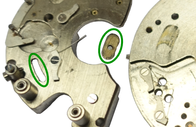
The stop of this limiting pin can be shifted within certain limits by means of a screw on the side of the movement:
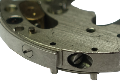
This allows precise setting of the time at which the contacts are closed in each case and that the contact is reliably reopened when it stops.
Finally, a group picture of all parts of the telephonometer movement:

