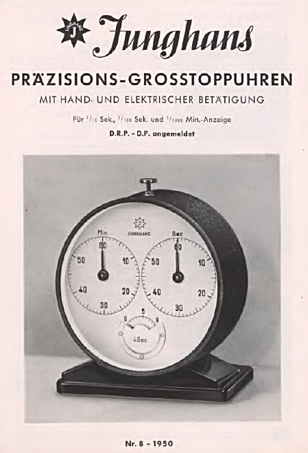
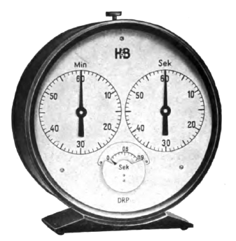
The three-circle stopwatches produced by Junghans since the 1950s in the format of a pocket watch are well-known design classics. However, Junghans also produced large laboratory stopwatches with a three-circle display.
I found the oldest reference to these clocks in a Junghans catalog from 1950. In a Junghans price list from April 1951, the version shown here is listed at 330 German marks. The oldest reference to the three-circuit pocket watch I could find stems from a Junghans catalog from 1956, but it was probably built from 1955 onwards. So the three-circuit laboratory clock has been around a little longer than the pocket watch.
The three-circuit laboratory clock was available in the following versions:
| Typ | Funktion |
|---|---|
| 310/0401 | Stopwatch for recording one-time processes. 1/10 second display |
| 310/0402 | Stopwatch for recording one-time processes. 1/100 second display |
| 310/0403 | Stopwatch for recording one-time processes. 1/1000 minute display |
| 310/0404 | Addition stopwatch for recording various consecutive processes. 1/10 second display |
| 310/0405 | Addition stopwatch for recording various consecutive processes. 1/100 second display |
| 310/0406 | Addition stopwatch for recording various consecutive processes. 1/1000 minute display |
| 310/0407 | Special addition stopwatch, requires the button to be pressed continuously for the duration of the measuring process or a continuous current for the actuating magnet. 1/100 second display |
All variants can be operated manually via one or two pushers and also via a current pulse or a continuous current in the case of the special addition stopwatch. In all cases, the watch must be wound by hand, even if the start, stop and zero setting are triggered electrically!
The type 310/0401 laboratory clock presented here has a diameter of 147 mm without base and a depth of 73 mm. The weight is around 1.6 kg.
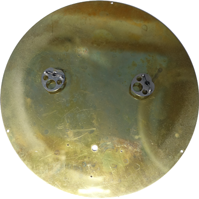
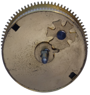
This is what the back of the watch looks like:
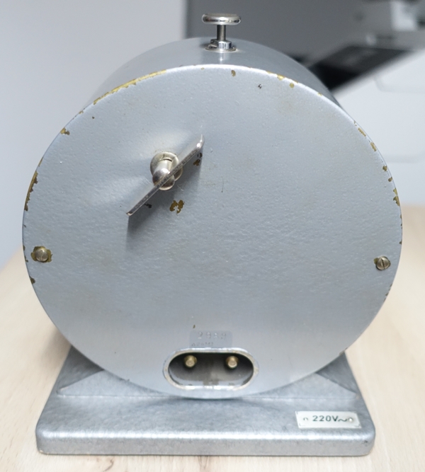
At the top is the screwed-on key for winding. To wind up, it is turned to the left; to remove the back, the key must be unscrewed to the right. The connectors for the electrical actuation are located at the bottom center. We’ll take a closer look at these in a moment.
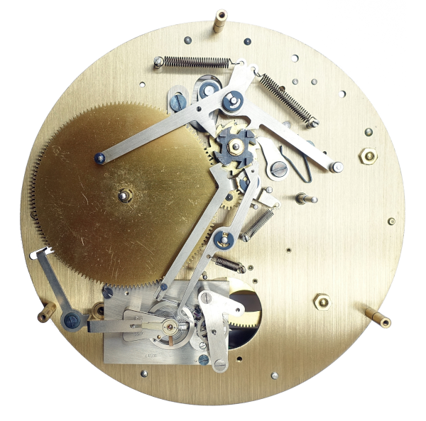
Let’s have a look inside:
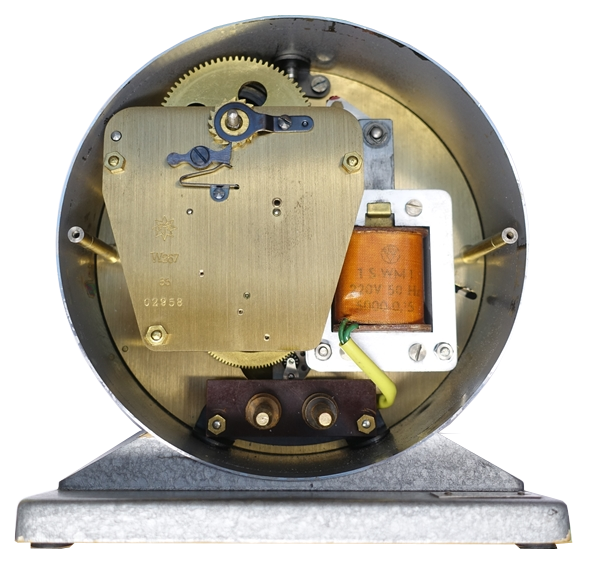
The movement has the caliber designation W267. To the right of it, you can see a rather large electromagnet.
The W267 and the J28 and W701 movements were developed by Hans Schlenker (1906 – 1984). As early as 1934, he patented a three-circuit stopwatch movement (German patent DE597698), which later became the J28 for pocket watches. This was followed in 1963 by the American patent US3077729 for a 1/1000-minute pocket stopwatch.
At the time of the first patent application, Hans Schlenker was an employee of Hartmann & Braun in Frankfurt. The company acquired a license from him and was the first company to manufacture large three-circle stopwatches, i.e. before Junghans. After the Second World War, Hartmann & Braun gave up the production of large stopwatches and returned the license. At the end of 1945, Schlenker became an employee of Junghans. Junghans acquired a license from him and he developed the W267 for Junghans.
To remove the internal components from the housing, you can proceed as follows:
- Remove the winding key (turn to the right)
- Remove the screws from the rear panel and pull off the rear panel
- Remove the screws on the base
- Loosen the screw of the pusher from the outside
- Remove the movement to the rear
- Caution: the glass is not secured and can fall out from behind!
- Remove the retaining rings from the minute and second hands and pull both hands upwards a little. The hands remain on the dial!
- Unscrew the cover of the 1/10 second hand
- Carefully lever off the 1/10 second hand
- Unscrew the dial and lift it upwards, including the hands
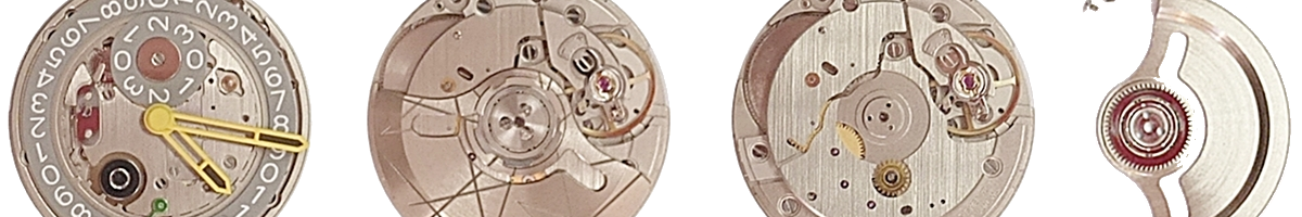
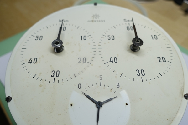
Removing the cover of the 1/10 second hand reveals a little surprise: it does not consist of one hand, but of three hands! Unfortunately, the discoloration and stains on the dial cannot be removed without causing damage.
As just described, the minute and second hands remain on the dial. Both have a so-called heart on the back of the dial. It ensures that the hand lands exactly on the zero position when the stopwatch is set to zero.
All the other components required for a stopwatch to function are located on the dial side of the movement. But let’s take a look at the back of the movement first.
Important note: Always release the mainspring before dismantling the movement. Otherwise it will abruptly release. This can result in damage to the movement and in injuries!
Here, the rear plate has already been removed:

The power flow (marked in green) goes from the mainspring barrel (1) via the large driving wheel (2), the fourth wheel (3) and an intermediate wheel (4) to the escape wheel (5). The third wheel of a classic wheel train construction is therefore missing between the large driving wheel and fourth wheel.
The following picture shows the section in which the intermediate wheel drives the pinion of the escape wheel:

The seconds counter is located on the dial side on the pivot of the fourth wheel, the 1/10 second counter on the pivot of the escape wheel, also on the dial side. The minute counter is driven indirectly by a pinion on the large driving wheel on the dial side.
The Junghans W267, including the electromagnet, has a diameter of 145 mm, a height of approx. 55 mm and a weight of 1,013 g. The power reserve of the 1/10-second version is 3.5 hours, while the 1/100-second version has a power reserve of just 25 minutes. There is a Maltese cross stopwork on the barrel, which ensures that the spring cannot be wound up to its full length and cannot run down completely. This ensures that the movement runs at a stable rate, but at the cost of some power reserve.
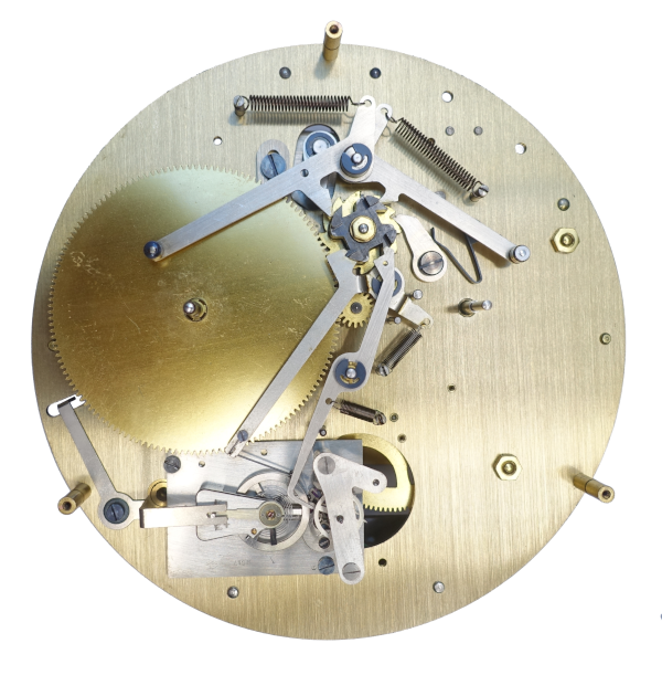
Now let’s take a look at the dial side of the movement:
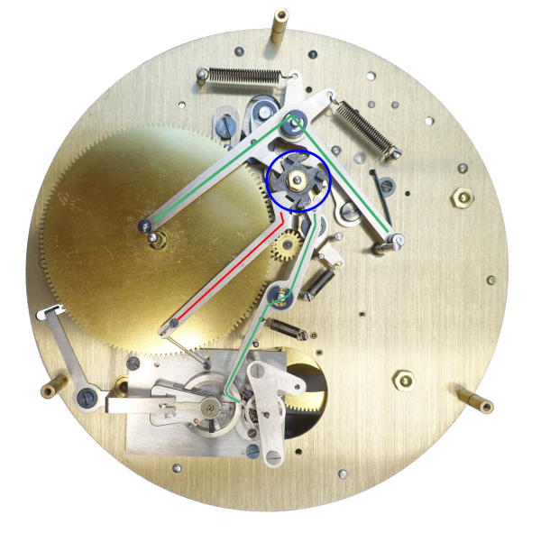
The large wheel on the left is the aforementioned wheel for the minute counter, which is driven at its right edge by the pinion on the main wheel. At the bottom left you can see an echappement, i.e. a module that carries the balance, the anchor and the escape wheel and is screwed onto the movement as a whole.

The Echappement bears the designation BEC17, has a nickel balance with Breguet-Nivarox hairspring, 9 jewels and the balance ticks at 36,000 bph (beats per hour). The 36,000 bph correspond to 10 ‘ticks’ per second, i.e. one per 1/10 of a second. This high oscillation frequency is essential in order to be able to measure 1/10 second units at all.
Incidentally, the rest of the movement has to manage without jewel bearings!
The components required for the stopwatch function (zero setting, start, stop) are also located on the dial side:
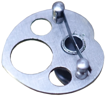
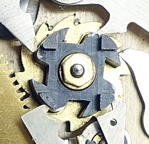
- The hammers(marked in green)ensure that the hearts shown above set the hands to zero. Two of them, the ones for the seconds counter and the minute counter, are classic heart levers. The third lever for the 1/10 second counter engages directly in a ring with three spikes that is pressed onto the escape wheel, so that the nearest spike is always blocked and one of the three 1/10 second hands comes to a stop at zero.
The following picture shows the spikes:
- The stop-seconds lever(marked in red)has a soft plastic roller at its end that is pressed against the balance when the watch is stopped, thus stopping the movement immediately.
- The column wheel(marked in blue)is advanced by one position each time the stopwatch button is pressed and ensures that the four levers just described assume the correct position each time the button is pressed:
| Button press | Hammer position | Stop-seconds lever position |
|---|---|---|
| 1. Start | Not in contact with the counters | Not in contact with the balance |
| 2. Stop | Not in contact with the counters | In contact with the balance |
| 3. Zero | In contact with the counters | Not in contact with the balance |
The gold-colored toothed wheel is advanced by one position each time the stopwatch button is pressed. As a result, the black column wheel also advances and the levers attached to it alternately land on a rise or in a depression, thus changing their position.
In the picture of the movement shown above, it is in the zero position. The two following pictures show it after starting in running condition and after stopping.
The following video also shows the change between start, stop and zero position:
Incidentally, the balance continues to run for a few seconds at the zero position, but the hands are all blocked.
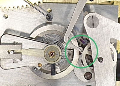
Finally, some information on the electrical control of the movement. With each current pulse the electromagnet pulls an iron core down. This is connected to the pusher mechanism of the movement. The mechanical pusher works at the pointmarked in greenin the picture, the electromagnet at the pointmarked in blue.
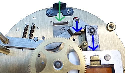
The clock must therefore not be permanently connected to the power supply, but only requires a short current pulse for each switching operation.
These laboratory clocks were supplied by Junghans with electromagnets for different voltage supplies (+/- 10 % in each case):
- 6, 12, 24, 110, 220 V DC voltage
- 110, 220 V AC voltage
My specimen is designed for 220 V AC voltage. Junghans specifies a power consumption of 35 W. I measured a resistance of 380 Ohm for the solenoid coil.
The connections on the back can be plugged into a hot appliance plug that was formerly used in Europe for waffle irons and irons, for example:
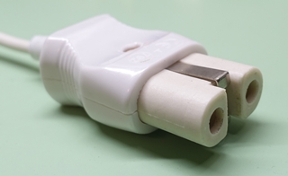
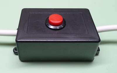
To ensure that the power supply is not permanently connected to the device, a push-button is connected in the line, which interrupts the line when not pressed (type NO = normally open). It is essential to use a 3-core mains cable with a protective earth connection, as the clock has a metal housing!
The above excerpt from the 1953 Junghans catalog shows a supplied impulse button that is led out of the back of the case. The interruption of the line therefore takes place inside this case. My specimen does not have a feed-through for such a button.
The video at the top of this article shows the laboratory clock with electrical control via the push-button.