The automatic movements of the 220 caliber family from the German manufacturer Bernhard Förster were very successful in the 1970s. Here we take a look at a few particular features of these movements.
First a little history
In 1907, Bernhard Förster, born in 1879, opened a jewelry manufacturing workshop in Pforzheim. Jewelry production was gradually expanded to include the production of watch cases and, from 1934, entire watches were manufactured under the name Foresta. From 1937, Förster also produced its own movements. These were not only used in the company’s own watches, but were also supplied to other manufacturers and brands, such as Dugena.

Förster movements are therefore not so rare. They are usually marked with the Förster logo and the caliber number.

[source: FORESTADENT Bernhard Förster GmbH]
After the factory was destroyed in the Second World War, a new production facility was set up in 1950. Fortunately, Förster had moved its production facilities to the surrounding area so that they were available for a new start. Förster became involved with automatic movements early on and gradually specialized in them.
Despite the success of the automatic movements, Förster also had to find new paths during the quartz crisis of the 1970s. In this case, these led away from watches and movements and towards dental technology, as the existing machinery and highly qualified employees were ideally suited to gaining a foothold here. The production of watch movements was discontinued in 1972. The company still exists today in Pforzheim as FORESTADENT Bernhard Förster GmbH and is managed by members of the Förster family. Unfortunately, the company no longer has anything to do with watches and movements.
The Förster automatic movements
The first Förster automatic movement was presented back in 1954 as caliber 80. It was based on the hand-wound caliber 50, to which a removable automatic module was added. As caliber 81, the movement was also available with a date dispay from 1956 onwards.
To save costs, the clutch winding system was replaced by a simpler rocking bar winding system in 1955. The caliber 80 thus became the caliber 800, based on the manual winding movement 500.
The original Caliber 80 was fitted with a Breguet coupling in 1957 to decouple the manual winding system from the automatic winding system and thus became caliber 90 without date and caliber 91 with date. This was followed by a caliber 191 with date, which probably had a simpler date mechanism and a modified rotor.
The caliber 192 introduced in 1960 consisted of the familiar automatic module and the hand-wound caliber 150 as the basis. The movement was a good one millimeter thinner than its predecessors, as the lower bridge of the automatic module was omitted here. Caliber 196 was accordingly the version with date. In 1962, these movements were further developed into calibers 194 (without date) and 197 (with date). They were given a screwless balance and a rotor locking mechanism patented by Förster (patent DE1188006).
The Förster 1197 with date and day display probably appeared as a variant around 1965.
Finally, in 1969, the Förster 220 followed as the first automatic movement of the new 200 family. We will discuss these automatic movements in the next section.
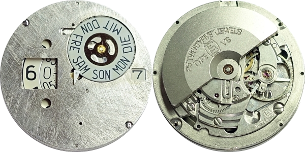
The 220 movements were supplemented around 1972 by the calibers 251, 253 and 255 with a diameter of 13 1/2”’. The only source I know of for these movements states that they all have a digital display. However, I own a Förster 253, which has a classic display of seconds, hours, minutes and date.
At the end of the automatic development in 1972 stood the only automatic movement from Förster for ladies’ watches, the caliber 420 and its derivatives 422, 426, 451, 453 with different functions.
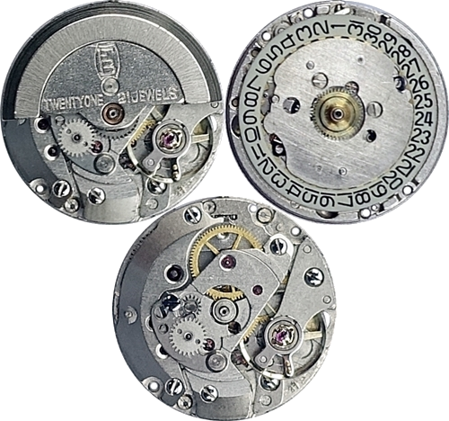
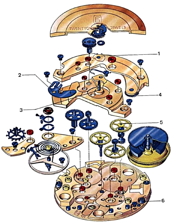
The automatic movements of the 220 family
The base movement of the 220 automatic movements was the Förster 200 with manual winding, which was the thinnest movement produced in Germany at the time around 1965 with a height of 3.5 mm.
The following variants of this family exist:
- 220: 11 1/2”’, no date
- 221: 11 1/2”’, no date, digital display of hours and minutes
- 222: 11 1/2”’, date
- 223: 13 1/2”’, date, digital display of hours and minutes
- 224: 11 1/2”’, date and day in separate windows
- 225: 13 1/2”’, date, day, digital display of hours and minutes
- 226: 11 1/2”’, date and day in a common window
- 228: 11 1/2”’, date on outer ring
All variants have a direct sweeping seconds hand, 25 jewels, a good 40-hour power reserve and the balance oscillates at 21,600 bph (beats per hour).
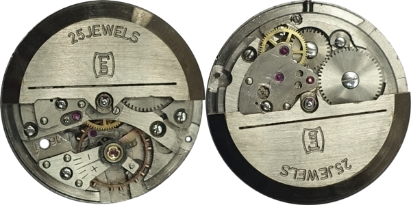
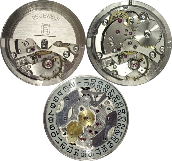
I can show three of the variants listed above here, the calibers 222, 225 and 226:
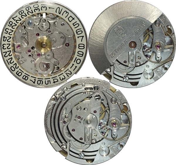
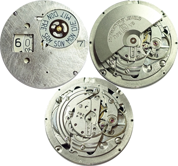
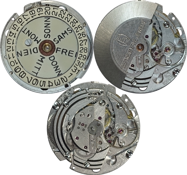
The bridge side is largely identical, as you would expect from a family of movements. Only the 225 has a slightly larger diameter of 13 1/2”’ instead of 11 1/2”’ due to the digital display. The staircase-like arrangement of the bridges is striking in all variants. This served to make the watch appear flatter. Small and flat was the order of the day at the time!
The movements were fitted with different shock protection systems. So far, I have come across the Incabloc, the Rufa Anti-Shock and the Antichoc S 65.
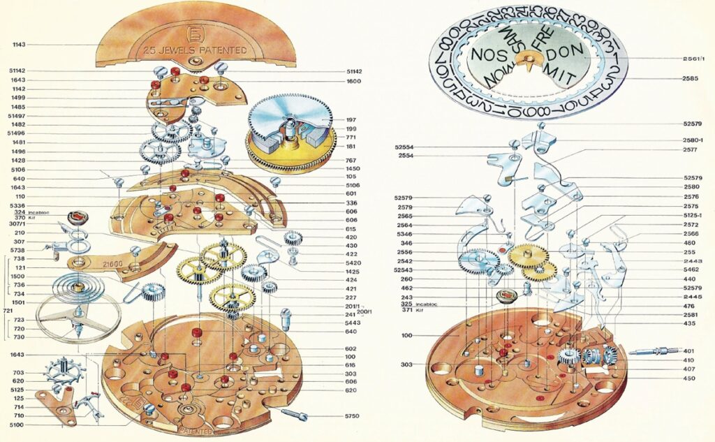
We will now take a closer look at the construction of some of the movement components using the Förster 226 as an example, in particular the automatic mechanism and the date and day switching mechanism.
The Base Movement
The base movement of the automatic family is the hand-wound Förster 200:
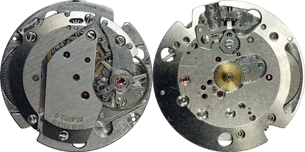
The movement has 17 jewels and an Incabloc shock protection. As with the automatic models, the balance oscillates at 21,600 bph (beats per hour) and the power reserve is a about 40 hours.
It is noteworthy that the crown wheel and ratchet wheel are located underneath the barrel bridge. The automatic can be placed on the bridge side of this base movement, and the components for the date and day display on the dial side. Date and day are of course also available for the hand-wound version.
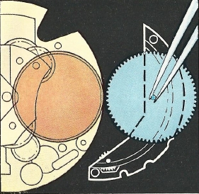
The base movement is designed in such a way that the mainspring barrel can be removed directly after removing the barrel bridge. Even when the automatic is fitted!
[source: Förster]
Date and Day
In normal operation, the date and day change immediately at midnight, i.e. not gradually and with a time delay, as was usually the case back then. Even today, there are still movements in which hours pass between the date and day changing!
The movement offers two options for setting the date or the day:
- Turning the hands back from 24 o’clock to 20:45 and set them forward again to 24 o’clock. This changes both the date and the day.
- Repeatedly pulling the crown past the point for setting the hands. This only adjusts the date, not the day. The hand position does not change either.
It therefore makes sense to first set the day using variant 1 and then the date using variant 2.
The following video shows variant 2 for setting the date:
And here the relevant component (blue):
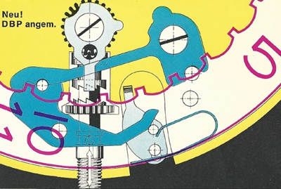
The next two pictures show the dial side of the movement without the day disk as well as a section of it.
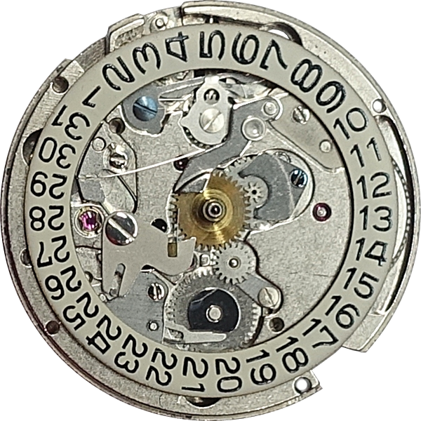

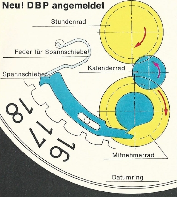
Part 1, marked in red, is the date driving wheel, which is driven by the hour wheel via an intermediate wheel. Part 2, the date corrector lever, is pushed upwards by a lug on part 1 and thus tensions a spring (hidden here under part 3). At midnight, the spring force causes the date corrector lever to fall back into its original position, thus turning the date disk. Part 3, the day finger, is coupled to part 2 and thus simultaneously ensures that the day is also advanced.
Here you can see the interaction of parts 1 and 2 in more detail:
The following video shows the mechanism that advances both the date disk and the day disk (removed here because of the better view). And towards the end of the video, variant 1 of the semi-quick setting of the date by turning back the hands.
All in all, a well sophisticated date mechanism!
Automatic
The following picture shows a section of the movement plate with the rotor removed. The area containing the parts for the automatic mechanism is marked in red. It is surprisingly small. The automatic unit cannot be removed as a module, as its lower plate is also the wheel train bridge of the base movement. This is of course due to the desire to keep the height of the movement as low as possible.
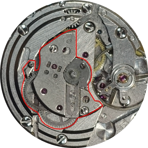
This is what it looks like under the automatic bridge:
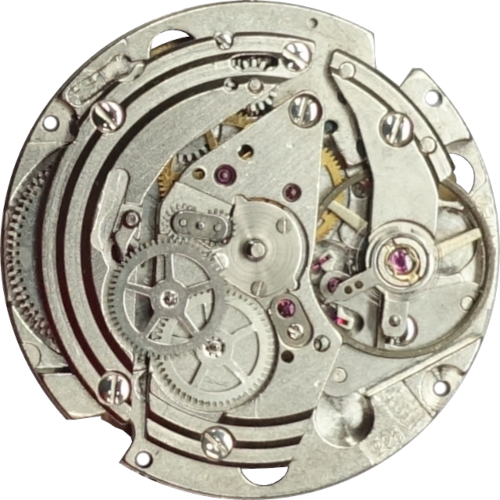
Let’s take a closer look at the components of the automatic:
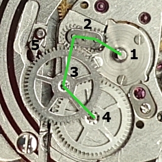
Part #1 is the rotor axis, part #2 is a rocking reverser, parts #3 and #4 are reduction wheels and part #5 is the automatic click.
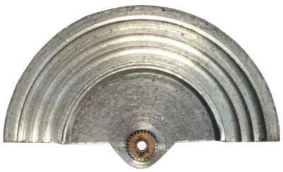
The rotor, which sits on the rotor axis, has a wheel on its back that always engages with the first wheel of the rocking reverser. The rocking reverser ensures that the first reduction wheel always turns in the same direction, regardless of whether the rotor is turning to the right or left!
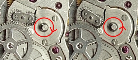
If the rotor turns to the right, the second wheel of the rocking reverser is in contact with the first reduction wheel. The first wheel of the rocking reverser turns to the left, its second wheel turns to the right and the first reduction wheel finally turns to the left.
If the rotor turns to the left, the first wheel of the rocking reverser is in contact with the first reduction wheel and the second wheel has no contact with it. The first wheel of the rocking reverser therefore turns to the right and the first reduction wheel turns to the left.
The following illustration shows the position of the rocking reverser for both directions of rotation of the rotor.
The two reduction wheels serve to translate the fast rotation of the rotor into a slower rotation with greater torque for winding the mainspring. And the click (part #5) ensures that the reduction wheels can only rotate in one direction and cannot run backwards.
The second reduction wheel has a pinion on its underside, which engages with the so-called wig-wag pinion at the point marked in red under the wheel train bridge in the next picture, which in turn turns the ratchet wheel at the point marked in green and thus winds up the mainspring. The right-hand part of the picture shows the same spot with the wheel train bridge removed.
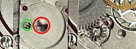
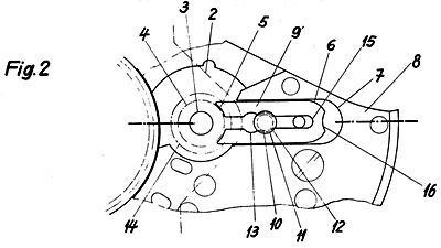
The wig-wag pinion decouples the automatic mechanism from the manual winding mechanism so that the wheels of the automatic mechanism are not rotated and stressed during manual winding. The following schematic diagram illustrates a little better how the wig-wag pinion works.
Translation:
Automatik-Trieb = automatic pinion
Sperrad = ratchet wheel
Umstelltrieb = wig-wag pinion
Umstellstift = wig-wag pinion pin
Feder für Umstelltrieb = spring for wig-wag pinion
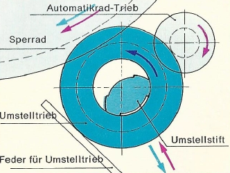
When wound by the automatic system, the pinion of the second reduction wheel (labeled automatic pinion in the picture) turns the wig-wag pinion (blue) and presses it against the ratchet wheel so that it winds the mainspring. The directions of movement are marked with purple arrows in the picture.
With manual winding, on the other hand, the ratchet wheel rotates. Its rotation pushes the pinion away from the ratchet wheel so that there is no longer a connection between the ratchet wheel and the pinion of the reduction wheel. Manual winding and automatic wheels are therefore decoupled. The directions of movement are marked with blue arrows in the picture.
Again, a very simple but effective mechanism!
Where actually are the 25 jewels in these automatic movements? The base movement has 17 jewels, the automatic 6. That makes a total of only 23! To get to 25 jewels, two cap jewels for the escape wheel were simply added to the base movement. Many jewels were definitely a selling point back then.

Hello,
Bought a vintage Foerster automatic wristwatch on eBay 2 years ago. A real bargain.
Watch has a 222 caliber and I am absolutely impressed with the performance and accuracy of this watch (incl. date window). Watch is ultra slim and can compete with any quartz watch caliber and I own a few of those. Thanks and congratulations to Mr.Foerster for his excellent work achieving the presentation of a mechanical/automatic watch caliber that is second to none of my quartz watches.